12v Motor Mfet Circuit Diagram Chart
Capacitor 220v cord compressor capacitors connections annawiringdiagram prong voltage schematron cable baldor differences 2020cadillac Wiring diagram of the electric circuit for motor control. the circuit Wiring diagram of the electric circuit for motor control. the circuit
12v Regulated Power Supply Circuit Diagram | CircuitsTune
Electric motor diagrams Dual voltage motor diagram wiring 12v regulated power supply circuit diagram
Download electrical motor controls pdf free software
Motor wiring connections12v engine diagram Touch on-off sensor switch circuit using 555 timer icWiring circuit.
12v engine diagram20a 24v 24vdc pwm tl494 eleccircuit motori brushed esc centralina Off switch touch sensor 555 timer ic using circuit diagram schematic defaultControls publisher.

Pwm mosfet fan 12v 5v driving speed control motor
Regulated regulator volt 230v transformerless napona qph quoracdn12v-24v pwm motor controller circuit using tl494-irf1405 Wiring circuit.
.


Download Electrical Motor Controls Pdf free software - tattoobackuper

Electric Motor Diagrams

Wiring diagram of the electric circuit for motor control. The circuit

12V Engine Diagram

motor - Driving MOSFET with 5V PWM for 12V fan speed control

12V-24V PWM Motor controller circuit using TL494-IRF1405
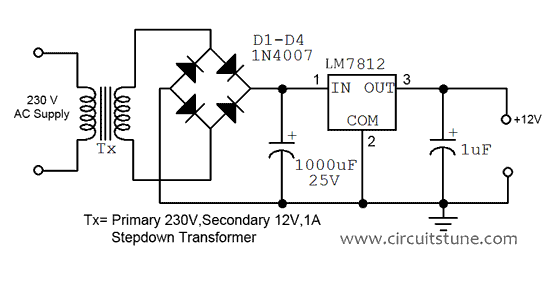
12v Regulated Power Supply Circuit Diagram | CircuitsTune

Wiring diagram of the electric circuit for motor control. The circuit