3 Wire Control Circuit
Wire parallax schematics circuits forums discussion Three-wire control circuit 6.7 2 and 3 wire control circuits for fluid power systems – hydraulics
How to wire VFD. Altivar 312 three wire control. - YouTube
How to wire vfd. altivar 312 three wire control. 3-wire control Ladder logic for special motor control circuits
Ladder diagram basics #3 (2 wire & 3 wire motor control circuit)
Motor button stop start diagram wiring starter circuit relay retain 480v control wire 120v push switch electrical symbol phase threeElectrical schematic Control wire circuit two l1 l2 figureCircuits divided.
Two wire & three wire motor control circuitStart/stop [3 wire] ac motor control Vfd wire control altivar threeWire two control circuit motor diagram three connected configuration motors controls turn only.

Ladder wire diagram control basics
3 wire motor controlControl basic circuits wire electric three equipment Control wire circuit systems hydraulics hydraulic electrical behavior describePost edited (jessica uelmen (parallax)) : 8/25/2010 6:32:51 pm gmt.
Wire motor control diagram circuit ladder basics3 wire motor control Three-wire control circuit with indicator lampStop diagram start wiring phase wire circuit three motor control industrial push two.

Control wire circuit circuits hydraulic systems hydraulics electrical behavior describe
Ladder diagram basics #3c 3 wire control6.7 2 and 3 wire control circuits for fluid power systems – hydraulics 3 wire output circuitCircuit control wire three start diagram motor button auxiliary ladder industrial push seal contacts coil connected.
How to wire a 2 wire control circuit for an ac drive vfd, toggle switchTwo wire & three wire motor control circuit 2 wire control vs 3 wire control. 2 wire control and 3 wire controlPlugging ladder motor control logic electrical circuit diagram circuits stop jogging engineering special anti wire wiring electric portal prevented torques.

Circuit control wire lamp three indicator wiring motor diagram ladder starter coil industrial when fig above energized added show
Wire control vsCircuit stop start diagram motor control wire two three multiple wiring jog switch starter electrical electricala2z stations configuration motors gif 3 phase stop start wiring diagramFigure 7-15.two-wire control circuit..
Basic control circuits:three-wire control circuitsWire vfd control circuit switch Control 220v contacts typicalCircuit wire output seekic basic diagram.


Three-Wire Control Circuit with Indicator Lamp

3 Wire Output Circuit - Basic_Circuit - Circuit Diagram - SeekIC.com

Figure 7-15.Two-wire control circuit.

Ladder Diagram Basics #3C 3 Wire Control - YouTube
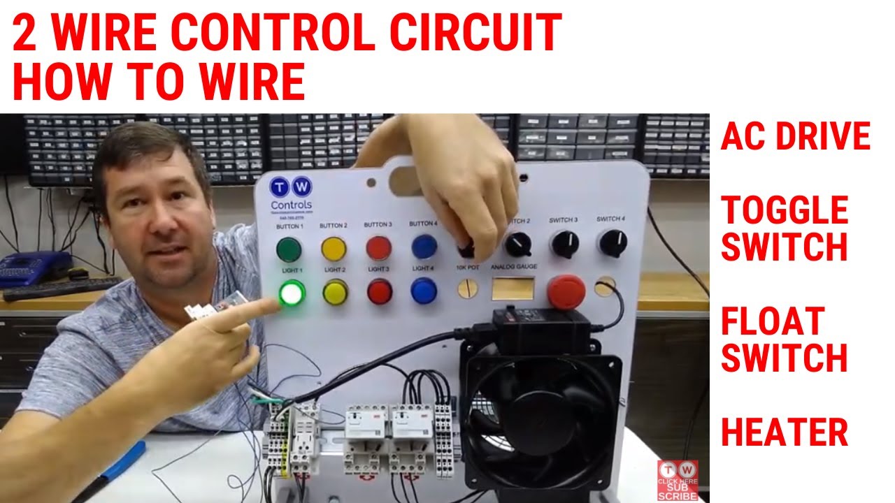
How to Wire a 2 Wire Control Circuit for an AC Drive VFD, Toggle Switch

3 Wire Motor Control

Post Edited (Jessica Uelmen (Parallax)) : 8/25/2010 6:32:51 PM GMT

2 wire control vs 3 wire control. 2 wire control and 3 wire control